Electrical Design
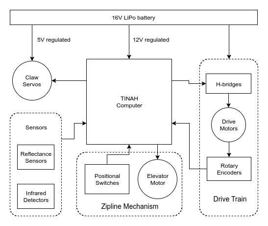
The Magic School Bot was powered by a single 16V lithium-polymer battery and controlled by a TINAH microcontroller board, which read inputs from the sensors, switches, and rotary encoders, and sent commands to the motors and servos.
Drive Train
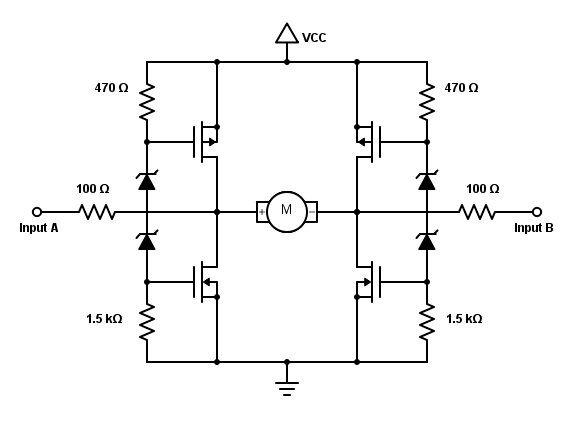
We used a rear differential drive with two H-bridge circuits to drive our motors at high power. Our H-bridges were constructed from discrete components based on the following design:
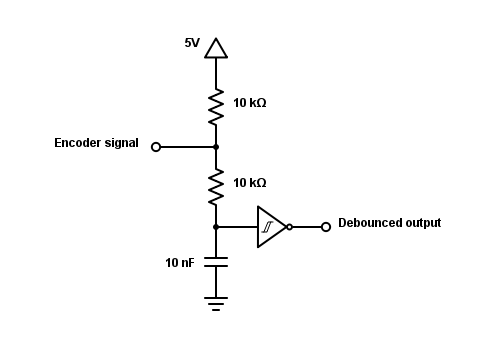
Since our initial robot design was heavily dependent on precise navigation to complete the course, we made use of two rotary encoders to provide accurate speed and direction feedback to the TINAH. The encoder signals were debounced using the following RC circuit.
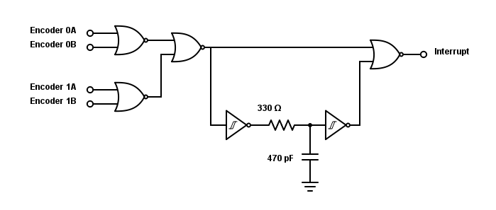
Additionally, the debounced output was filtered through an edge detection circuit, which was connected to an interrupt pin on the TINAH to ensure that no pulses would be missed.
Sensors
Our robot used four reflectance sensors (QRD1114) to follow tape and detect intersections, as well as two IR sensors (QSD124) to detect infrared light intensity. To detect infrared beacon pulse frequency, we used software filtering. This greatly simplified our electrical sensing circuit design.