Mechanical Design
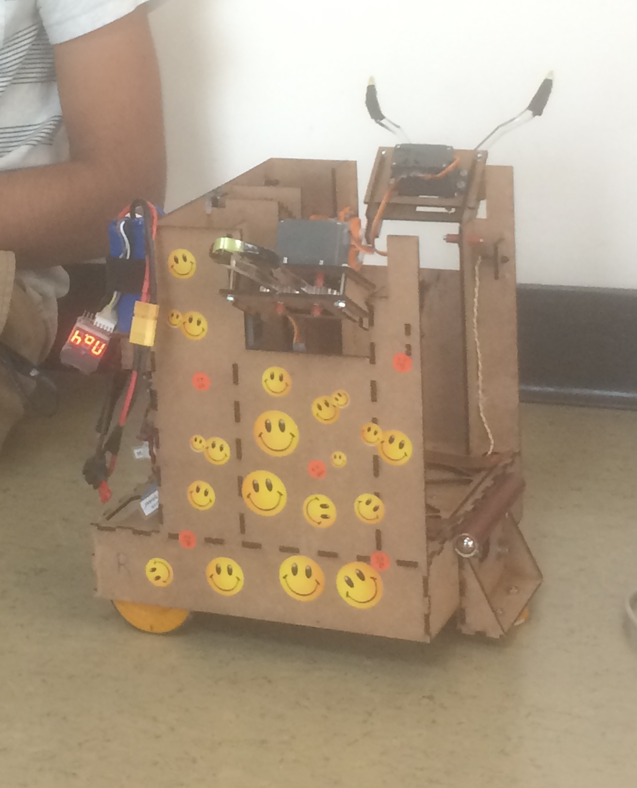
Since we registered our team with the name “Walkerville Elementary”, it seemed a forgone conclusion to make our robot magic school bus themed. Whether we succeeded in making it resemble a school bus is up to interpretation, but our robot was built using solid principles of mechanical design.
Overview
While designing our robot, we wanted the mechanical parts to be simple as possible for easier fabrication and troubleshooting. As such, we opted to construct the robot completely from hardboard instead of using sheet metal. This let us quickly create our parts on the laser cutter and assemble them, increasing our efficiency.
Chassis
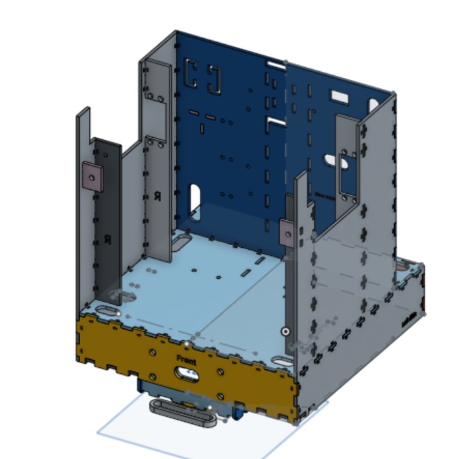
To build our chassis, we designed it using onshape, cut the individual pieces on the laser cutter, and assembled it. Our final design had the electronic circuitry mounted inside the chassis base, while the TINAH board and batteries were rear mounted for easy accessibility. The basket, zipline mechanism, and claws were mounted on top. During the 5 weeks of build time, we went through many iterations of the chassis as we made improvements to the design.
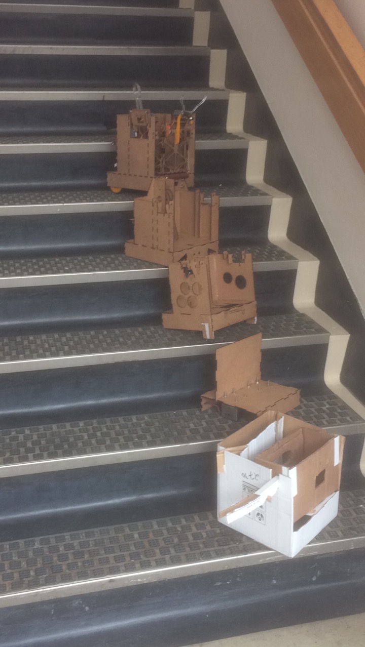
The evolution of our chassis
Claw
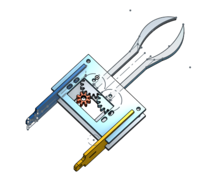
Similar to the chassis, the claw was designed in onshape, cut using the laser cutter, and assembled. Unlike the chassis which is glued, the claw is held in place by screws. To compete efficiently on both competition surfaces, we opted to have a claw on both the left and right sides of the robot. As such, the claws are small and fold inward when not in use the robot can get through the 12 inch by 12 inch gate at the beginning of the course.
Drive Train
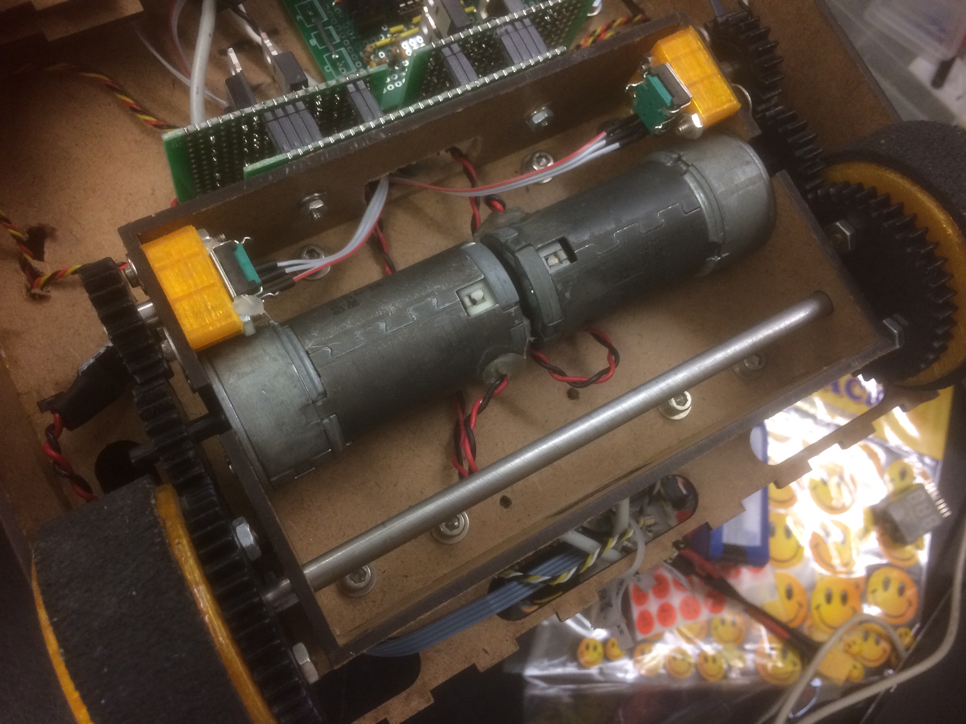
Again, the drive train was designed in onshape, cut using the laser cutter, and assembled. The robot is powered by Barber-Coleman motors geared at a ratio of 2:1. Additionally, we attached encoders to keep track of distances travelled. The encoders gave us a bit of trouble when they started breaking down after time trials, but since we had been keeping a good timeline we were able to replace the encoders and fix the issues in a timely manner.
Zipline Mechanism
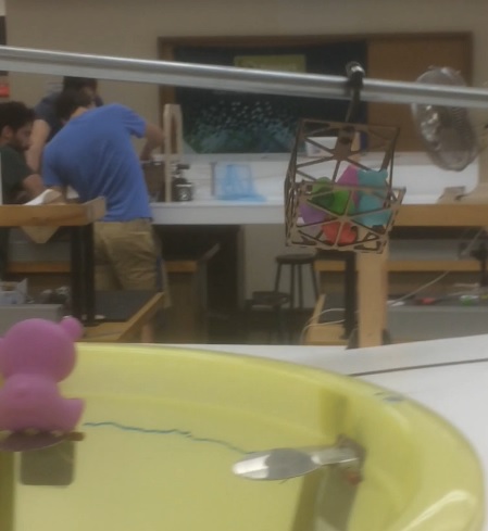
Agents making their escape
We opted to only send a basket with agents down the zipline, since that was less weight that the motor had to lift. Our lifting mechanism consisted of a 2-hinged arm driven by a motor at the base. The upper segment was constrained to be upright at all times and had a platform which the basket rested on.